

5 tips to speed up your Alias workflow.
Autodesk Alias is a powerful software tool, but with great power comes great complexity. As a result, there are often multiple ways to accomplish the same task, and each user may have their preferred method. This can make it challenging to get started with Alias.
Whether you are a beginner or a seasoned user, here are my top five tips to help you get the most out of the software and make your daily work with Alias easier:
1: Offset of 0mm.
In the early stages of a project, a designer may ask if the lamp graphics can be cut in. While this is possible, it will delete the construction history, and the designer is likely to ask if the lamp can be moved next. This means doing the lamps all over again. To preserve as much history as possible, there's a way to divide surfaces while keeping the original construction history intact. The trick is to offset by 0mm and trim as required. Here's a simple example to illustrate this approach:

Step 1:
In this example, I will use a simple square. First, I will offset it by 0mm, using the offset mode "original" to maintain the same CV layout. Next, I will project my graphic onto both the square and the offset at the same time. In this case, I will do a straight-down projection “curve on the surface” of a circle.

Step 2:
Trim out the surfaces as needed; I usually use my original surface as the outer trim and the offset as the graphic surface. Apply different shaders to the original square and offset to observe the effect.

Step 3:
You can move the original square around using its original construction curves, and the graphic will follow suit. While Trim Divide may achieve the same result, it will delete the original history, and if you move one, the other won't follow. Additionally, this method works across multiple surfaces in precisely the same way, but the offset is a separate group, making it much easier to identify later on.
2: Project curves onto surfaces.
The ultimate aim is to create smooth surfaces from smooth curves, whether for prototypes or high-quality work, as this simplifies the entire process. However, managing multiple curves in a 3D space and building clean surfaces from a curve-on-surface can be quite challenging. To simplify the process, we can use a construction surface and a basic set of curves in a 2D view to control Curves-Projected-On_Surface and have a much cleaner starting point.

Step 1:
In this example, I have created a standard set of curves for a wheel arch and a vertical draft surface positioned approximately where I want the arch to be. I have offset the arch a couple of times to give it some depth. The surface is flat and controlled by a single curve on its top edge.

Step 2:
To create the Curves-Projected-On-Surface, I project the inner curves onto the first surface from a side orthographic view. These curves are different from a curve-on surface because they're actual NURB/Bezier curves that sit on the surface and maintain the history of the original projecting curve and the surface they sit on. To preserve the original curves' parameterisation and structure, check the "Original" box.
Repeat these steps for the other curves and offset surfaces.

Step: 3
Construction surfaces can now be templated and hidden. (We still need them for their history, but we don’t need to see them) The Freeform blend tool can be used to add simple surfaces between curves.

Step 4:
We can return to our curve control and adjust the draft surfaces by moving the control vertices to obtain the desired shape. As the construction history updates, the drafts will move and pull the blends while maintaining the original side view shape.
This technique can be utilized for various applications, including IP-door plan shapes, door pockets, spoilers, and any other scenario where you need to manage a 2D set of curves in 3D space. You could even align the edges of the drafts to control how the lines fade out, for instance.
3: Paste Options.
When I first discovered it, this one was a game-changer. Open the option box for paste in the edit menu and select Always Ask. Now, when you paste something, it will ask what layer you want it to go in or what you want to do with it. No more pasting stuff and wondering where it went or having to fish it out of an already packed layer.
4: Straighten curves with a construction plane.
One of the most common issues in surfacing, especially with exteriors, is the appearance of wobbly curves. This problem is most noticeable in features such as belt lines that run the entire length of a vehicle. As you adjust the curve, it can cause other parts to move, resulting in inflexions and wobbles. When building surfaces from these curves, your highlights will follow the intersection curve, resulting in wobbly highlights as well. To simplify the process and achieve a more controlled 3D curve, we can build a construction plane along the core of the curve, which will allow us to achieve a nice, taut curve.

Step 1:
This is a simple example of a typical exterior body-side/beltline setup. With the curvature comb on, you can see just how wobbly it is. When a blend is applied, there will be flat spots and inconsistencies in the highlights.

Step 2:
To fix this, start by snapping a simple keypoint curve to the first and last CVs (1). Then, using the perpendicular curve tool, draw a line from the centre of the keypoint curve out to the beltline curve (2). This sets up the axis for a construction plane. Snap it to the centre point (3), then use the green rotate ball to snap to the end of the perpendicular curve and the red rotate ball to snap to one end of the keypoint curve. Now set the construction plane to be active.

Step 3:
In a side orthographic view, we can now see exactly where the curve inflects. Select all the CVs except the first and last of the belt line curve and snap them down in Z to the grid (Move tool >Alt+right click). The curve is now completely flat along its length but still maintains its shape in other views.

Step 4:
To achieve a clean curve, move to a top orthographic view and adjust the CVs in the X and Y directions only. This will keep the curve flat in side view, making it easier to control. Once you are satisfied with the curve, turn off the construction plane to return to normal 3D space.

Step 4:
We can now see a significant improvement in our curve. By adding a blend to the surfaces, we achieved clean and consistent highlights. This technique is effective for curves of any size and can greatly enhance a design's sharpness and quality impression.
5: Use instance for symmetrical squares.
Creating symmetrical surfaces across the centre line is a crucial skill in surfacing. There are various helpful tools for achieving this, but issues arise when you need to control curves or surfaces that are mirrored but do not intersect the centre line. For instance, when building a bumper or roof surface, you might need to use the Square tool to control all four edges. This technique ensures that the surface remains symmetrical and retains the construction history, allowing for quick updates in the future.

Step 1:
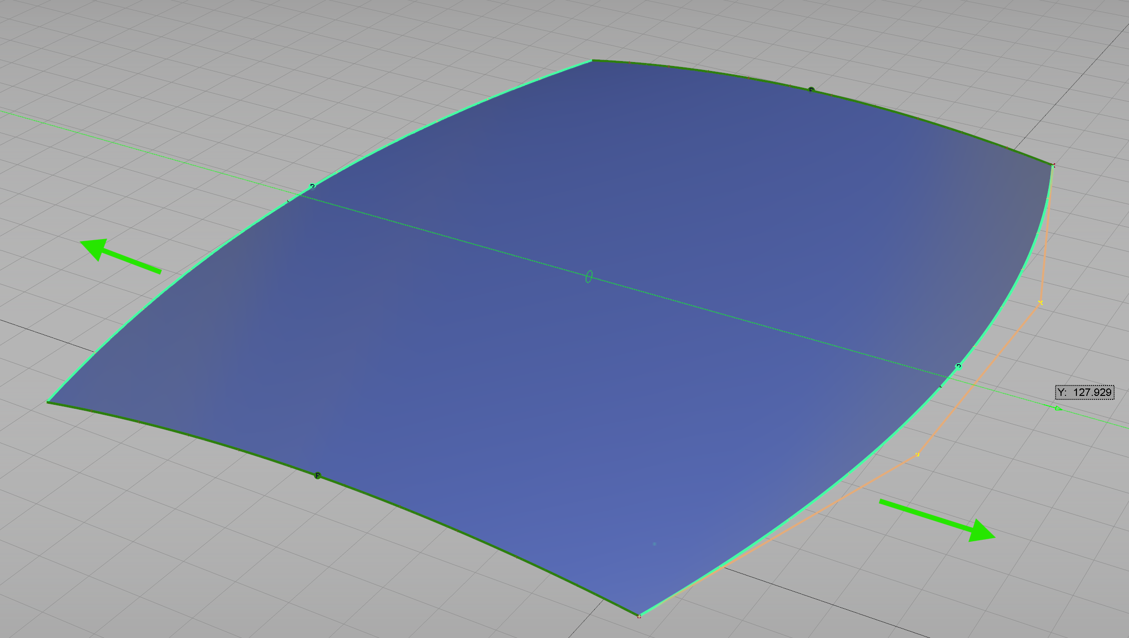
To create a simple roof surface, add two curves that intersect with the Y0 axis (1 & 2). These curves represent the roof's leading and trailing edges. Use the symmetrical modelling tool to ensure symmetry. Then, add a simple Deg3 curve that joins one end of the symmetrical curves (3). This will help complete the roof surface.

Step 2:
Pick the degree 3 curve and set its pivot to Y0. Then, open the duplicate options box, set the Y scaling to -1 (this will mirror the curve about Y0), and check the create instance box. This will create a mirror of the curve that will match any changes you make to the original. Note: Alias will only show CVs on the original curve but will highlight both curves as selected.
Step 3:
To create a square, start by using the four curves. Afterwards, you can move the control vertices (CVs) to adjust the shape of the square. As long as you keep the two corner points of the original curves connected, the square will remain symmetrical across Y0 and update automatically.
This technique is handy for various surfacing problems. It is important to note that it can be applied to anything with layer symmetry, such as a seat. To do this, you can establish a construction plane at the centerline of the seat and then set the layer symmetry to that plane. This effectively relocates Y0 to the centre of the seat. This method can also be used for steering wheels and columns and anything that can be created symmetrically.
I hope you found something useful here. In future posts, I will expand on some of these techniques and focus on getting the most out of the individual tools used. Make sure to subscribe to receive all the latest updates!

5 Essential Alias hotkeys
Hotkeys are an incredibly useful way to speed up your workflow and Alias helpfully allows you to customise them as you need. These are 5 of my favourites that I use everyday.

Hotkeys are an incredibly useful way to speed up your workflow and Alias helpfully allows you to customise them as you need (Click here to find out how). Here are 5 of my favourites that I use everyday. When assigning a hotkey, try to think of a combination of keys that’s easy to reach, most of mine pivot around the alt or ctrl keys as that’s where my left hand is most of the time to move the model around so keeping my thumb on Alt and reaching to a nearby key is easy and doesn't stretch my hand to much.
1 - Alt Key:
Not really a hotkey as such but when switching stages, press the alt key when you click on a stage to set the working level and visibility to that stage only as if you only had one stage open. This works in both the drop down stage list and the stage editor.
2 - Cv's On and Off:

Apart from Ctrl+C and Ctrl+V these are possibly my most used hotkeys. I set Alt+A and Alt+S to switch the control points and Isoparm’s on and off for the selected objects.
3 - Toggle Tool Window:

Similar to a query edit the toggle tool window allows you to edit an object with history by bringing up the tool options. To save time set the toggle to an easy hotkey, select an object and press the hotkey to edit the object.
4 - Blend curve alignment:

A useful one if you use blend curves a lot. I often need to switch a blend curve from its default G2 setting to G1 or sometimes G3. To do this quickly, select the blend edit point and hit the hotkey, I set a hotkey of Alt+1, 2 or 3 for constraint continuity for G1 to G3 respectively.
5 - Toggle Visibility:

If you often use "hide unselected" this one can be really helpful. Set a hotkey for toggle visibility so when working on some isolated surfaces you can quickly toggle back to the hidden objects to pick some extra surfaces or objects, make them invisible, and then use the hot key to toggle back to your isolated surfaces.
I hope these help with your daily workflow. Try to think of things you do all the time that could be simplified by using a quick hotkey and remember don’t overstretch to reach them!
Make sure to subscribe to all the latest updates!

Work in progress
The Not Yet Finished One:
After finishing the IAD Alien I was thinking of some ideas for what build next when I found some old photos of my final year project at university, a modern Auburn 851 Speedster…
The Not Yet Finished One:
After finishing the IAD Alien I was thinking of some ideas for what build next when I found some old photos of my final year project at university, a modern Auburn 851 Speedster. The car was to be an electric hybrid aiming to show that environmentally friendly cars didn’t need to be boring. While the idea is common nowadays in 1996, when I started this project, it was not much more than a pipe dream. Armed with a bunch of photos of the finished model, the last few remaining sketches from an old portfolio and knowing i had originally used a 1996 model year Corvette as a reference for wheel base and overall package I set to work.

This is work in progress and a long way from being finished, but I will post more updates here as I progress…